
BMW Z4 E85 FUEL PUMP 2003-2005

BMW Z4 E85 FUEL PUMP
Fuel System – Repair Procedures – Z4/E85
FUEL PUMP WITH DRIVE AND LINE
Feature of this version with ambient pressure:
The connection for the vacuum hose of the fuel pressure regulator is located between the throttle and the air cleaner or on the air cleaner.
Test precondition:
The correct fuel pressure regulator is fitted.
{ Using the EPC, check whether the fuel pressure regulator suitable for the car is fitted:
Connect test adapter. See 13 31 029 Checking Fuel Pump Delivery Pressure (M54)
Description of operation:
The control function of the fuel pressure regulator must be guaranteed under all operating conditions. The fuel pump must always be able to generate a higher fuel pressure than the pressure regulated by the pressure regulator.
The injection rate is adjusted by means of the injection time; the injection time is controlled by the DME.
Description of operation: fuel return line
When the engine is at a standstill and the ignition key is in position 0, the fuel return line after the pressure regulator is at zero pressure.
Description of operation: pressure retaining function
The pressure regulator closes when the engine is at a standstill and the ignition key is in position 0. The fuel pressure in the delivery line is retained over an extended period. A non-return valve closes in the fuel pump.
These measures help to retain the fuel pressure in the fuel system. Extended starting times are thus avoided.
Complaint: drive characteristic faults, lack of power
{ Run engine at idle speed and measure fuel pressure.
If the measured value is less than the nominal value – 0.2 bar:
{ – Line cross-sections in fuel feed are constricted or fuel filter is clogged,
or
{ Fuel pump voltage supply is not O.K.: e.g. as a result of high contact resistance (corrosion) in plug
connection between wiring harness and fuel pump.
If the measured value is greater than the nominal value + 0.2 bar:
{ Turn off engine stop and then observe measured value.
{ If measured value drops to nominal value, then line cross-sections in fuel return are constricted or clogged.
{ Check the fuel lines for kinks.
If no kinks are visible:
{ Replace return lines If measured value remains too high, then pressure regulator is in all probability faulty.
important:
With less likelihood, the return line may be completely blocked. When the pressure regulator is removed, fuel could escape under pressure!
{ Have a cleaning cloth ready and catch and dispose of escaping fuel.
{ Replace the return line but not the pressure regulator.
Complaint: starting problems
{ Run engine briefly at idle speed and switch off.
{ Note down measured value while engine is stopped.
{ Read off measured value again after approx. 20 to 30 minutes while engine is stopped.
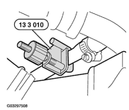
Special tool 13 3 010 (hose clamp) is required for the following test.
If the measured value has dropped by more than 0.5 bar:
{ Start engine and wait briefly for a stable pressure increase.
{ Switch off the engine and immediately pinch off the delivery line just before the pressure gauge with the special tool 13 3 010.
{ Note down measured value
{ Read off measured value again after approx. 20 to 30 minutes while engine is stopped
the measured value has now dropped by less than 0.5 bar, the following faults can be present:
{ Fault in delivery lines
{ Fault in in-tank delivery hose
{ Faulty pressure-holding non-return valve in fuel pump
Check components. Replace faulty components.
If the measured value has dropped by more than 0.5 bar again:
{ Replace pressure regulator
BMW Z4 FUEL PUMP
13 31 029 CHECKING FUEL PUMP DELIVERY PRESSURE (M54)
Special tools required:
z 13 3 010
z 13 5 220
z 61 3 050
Switch off ignition.
Catch and dispose of escaping fuel.
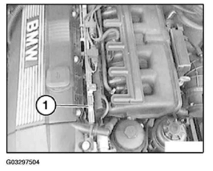
Remove cover from fuel injectors.
Remove dust cap (1) from measuring valve on fuel rail.
NOTE:
{ All the fuel hoses and hose clips which were detached within the
framework of the checks must be replaced.
{ Interrogate fault memory of DME control unit. Check stored fault
messages. Rectify faults. Now clear the fault memory.
CAUTION: The fuel in the fuel lines is under pressure (approx. 3 bar)!
Removing Dust Cap From Measuring Valve On Fuel Rail
Fig. 1: Removing Dust Cap From Measuring Valve On Fuel Rail
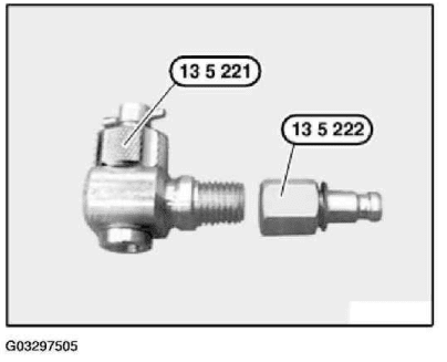
Prepare special took kit 13 5 220 (consisting of 13 5 221 and 13 5 222).
Fig. 2: Assembling Special Took Kit
Unscrew check valve (1) on special tool kit 13 5 220.
Fit special tool kit 13 5 220 on measuring valve and tighten knurled nut until hand-tight.
Start engine.
Screw in check valve (1) until a pressure reading is indicated on DIS Tester.
CAUTION: Do not under any circumstances screw in the check valve up to the
mechanical stop. This could damage the valve in the pressure regulator
housing.
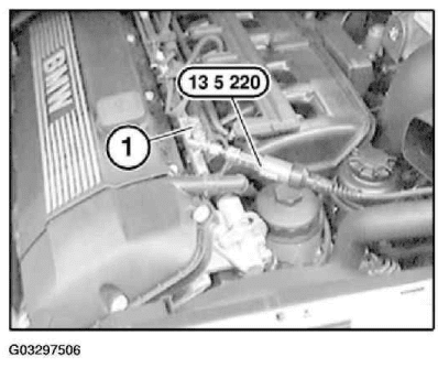
Connecting Special Tool Kit On Measuring Valve
Courtesy of BMW OF NORTH AMERICA, INC.
Measuring fuel pressure:
{ Connect pressure sensor to DIS Tester
{ Start engine.
{ Select Measurement.
{ Multimeter function appears
{ Select Pressure test
{ Read off fuel pressure
Compare actual value of test pressure with specified value. See FUEL SYSTEM – TECHNICAL DATA .
Switch off engine.
Checking fuel pump:
pump relay. See RELAYS .
Connect special tool 61 3 050 to terminal (87) and terminal (30).
Press button and read off fuel pump delivery pressure on DIS Tester.
Compare actual value with specified value of delivery pressure.
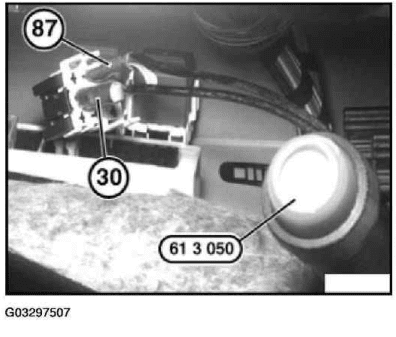
Fig. 4: Connecting Special Tool To Terminal 87 And 30
Courtesy of BMW OF NORTH AMERICA, INC.
Keep special tool 13 3 010 ready for further tests.
Further tests are described in 13 31… Notes On Fuel Pressure Check (Reference Pressure: Environment)
NOTE: Check whether fuel pump no longer starts up during engine starting procedure
(engine fails to start).
Installing Special Tool
Courtesy of BMW OF NORTH AMERICA, INC.
Check stored fault messages.
Rectify faults.
Then clear fault memory.
SPEED GOVERNOR
13 41 500 REPLACING IDLE SPEED CONTROL VALVE (M52TU, M54)
Necessary preliminary tasks:
NOTE: Interrogate fault memory of DME control unit.
Switch off ignition.
z Disconnect battery ground wire.
z See 12 00… INSTRUCTIONS FOR DISCONNECTING AND CONNECTING BATTERY .
M52TU only:
Remove intake filter housing.
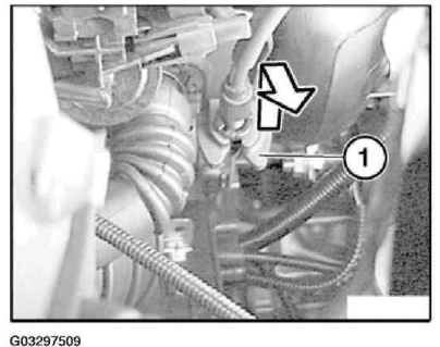
Pull Bowden cable upwards out of holder (1) and suspend from throttle.
Fig. 6: Removing Bowden Cable From Holder
Courtesy of BMW OF NORTH AMERICA, INC.
Loosen hose clamps (1).
Detach air intake hose section from throttle assembly and idle actuator.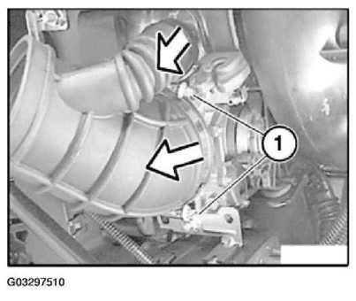
Fig. 7: Detaching Air Intake Hose Section From Throttle Assembly And Idle Actuator
Installation:
To facilitate installation, fit air-mass flow sensor with intake hose (1). Coat intake hose (1) with anti-seize agent.
Air-Mass Flow Sensor With Intake Hose
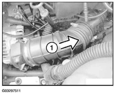
Fig. 8: Fitting Air-Mass Flow Sensor With Intake Hose
M54 E46/E53 only:
Remove complete intake hose (between intake filter housing and throttle assembly).
M54 E60/E61/E65/E66 only:
Remove intake hose.
M52TU and M54:
Unfasten following plug connections:
1. Resonance flap
2. Idle speed control valve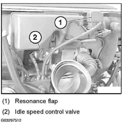
Fig. 9: Releasing Resonance Flap And Idle Speed Control Valve
Courtesy of BMW OF NORTH AMERICA, INC.
Installation location:
Idle actuator (2) is fitted below intake air manifold, directly above throttle (1).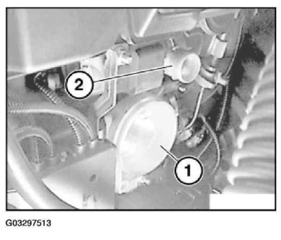
Fig. 10: Locating Idle Actuator
Courtesy of BMW OF NORTH AMERICA, INC.
Release screw (1) on cable duct mounting.
Release screws (2) on holder of idle actuator (3).
Remove idle actuator with holder from intake air manifold.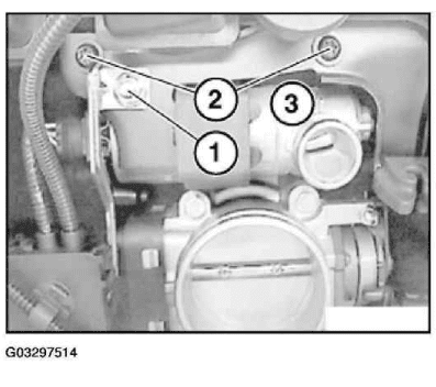
Fig. 11: Removing Idle Actuator With Holder From Intake Air Manifold
Courtesy of BMW OF NORTH AMERICA, INC.
Detach idle actuator (2) from rubber retainer (4).
Always replace gasket (1) from idle actuator (2) to intake air manifold. However, during reinstallation, do not
fit gasket on idle actuator but install first in intake air manifold.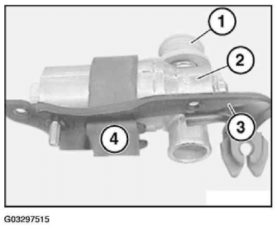
Fig. 12: Detaching Idle Actuator From Rubber Retainer
Courtesy of BMW OF NORTH AMERICA, INC.
Installation:
Replace seal (1).
Coat gasket (1) on inside with antiseize agent.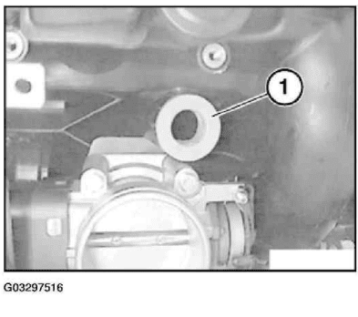
Fig. 13: Replacing Seal
Courtesy of BMW OF NORTH AMERICA, INC.
Check stored fault messages.
Rectify faults.
Then clear fault memory.
INJECTION NOZZLE AND LINES
13 53 240 REPLACING COMPLETE INJECTION PIPE (M54)
Necessary preliminary tasks:
NOTE: Interrogate fault memory of DME control unit.
Switch off ignition.
z Remove cover for fuel injectors.
Unclip plug connections (1) from holders and disconnect.
When replacing injection pipe:
Remove both holders for plug connections (1) from injection pipe.
Disconnect plug connection of intake air temperature sensor (2).
Disconnect plug connection (3) on solenoid valve of VANOS adjustment unit.
Detach terminal strip (4) for fuel injectors from injection pipe.
Recycling
Fuel in fuel lines is under pressure (approx. 3 – 5 bar). Fuel escapes when fuel lines are detached. Catch and
dispose of escaping fuel.
Observe country-specific waste-disposal regulations.
CAUTION: Mark plug connections (1) of oxygen monitor sensors for cylinder banks 1-
3 and 4-6 to prevent them from being mixed up when they are installed
later.
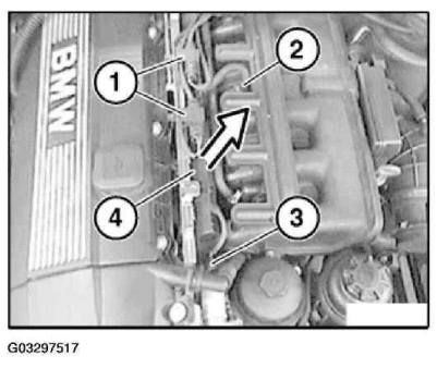
Fig. 14: Disconnecting Intake Air Temperature Sensor Plug Connection
Courtesy of BMW OF NORTH AMERICA, INC.
Z3, E85, E39, E46 and E53:
Unclip fuel line (1) from holder (2).
Follow instructions for unlocking fuel line.
Unlock fuel line (1) from cylinder head at rear.
NOTE: For a better overview, this work step is shown on an engine that has been
removed.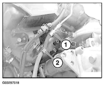
Fig. 15: Releasing Fuel Line From Holder
Courtesy of BMW OF NORTH AMERICA, INC.
Release screws (1) and remove injection pipe with fuel injectors.
Installation:
Coat sealing rings of fuel injectors with anti-seize agent to facilitate fitting of injection pipe.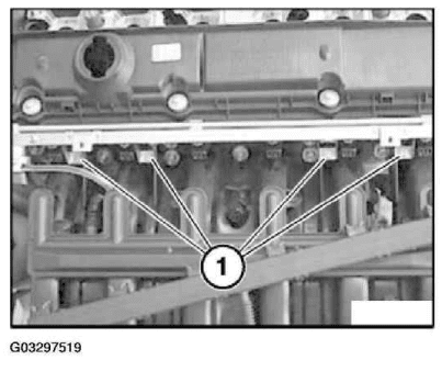
Fig. 16: Removing Injection Pipe With Fuel Injectors
Courtesy of BMW OF NORTH AMERICA, INC.
13 53 540 REPLACING, SEALING FUEL HOSES
Recycling
Catch and dispose of escaping fuel.
Observe country-specific waste-disposal regulations.
Version with hose clamps:
Release hose clamps.
WARNING: The fuel in the fuel lines is under pressure (approx. 3-5 bar)!
2005 BMW Z4
2003-05 ENGINE PERFORMANCE Fuel System – Repair Procedures – Z4/E85Remove hoses (1) and (2).
Installation:
Fuel hoses and hose clamps must be replaced each time they are removed!
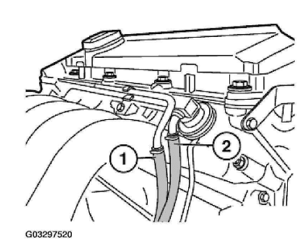
Fig. 17: Removing Hoses
Courtesy of BMW OF NORTH AMERICA, INC.
Version with compressed air connection:
Blow fuel back into tank with a short blast of compressed air (max. 3 bar) at compressed air connection (1).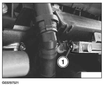
Fig. 18: Locating Compressed Air Blowing Point
Courtesy of BMW OF NORTH AMERICA, INC.
Version, fuel hoses without integrated unlocking facility:
Unlock fuel hoses with special tool 16 1 050 and detach hoses.
Installation:
Check O-ring in fuel hose and sealing surfaces on fuel lines for damage; replace components if necessary.
Coat O-ring for assembly with anti-friction agent.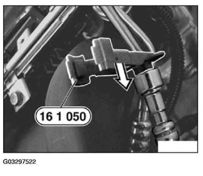
Fig. 19: Detaching Fuel Hoses With Special Tool
Courtesy of BMW OF NORTH AMERICA, INC.
Fuel hoses with integrated unlocking facility:
Press fuel hose (1) downwards and keep pressed.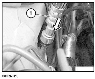
Fig. 20: Pressing Fuel Hose Downwards (Fuel Hoses With Integrated Unlocking Facility)
Courtesy of BMW OF NORTH AMERICA, INC.
Press unlocking ring (2) upwards, keep pressed and detach fuel hose (1).
Installation:
Check O-ring in fuel hose and sealing surfaces on fuel lines for damage; replace components if necessary.
Coat O-ring for assembly with anti-friction agent.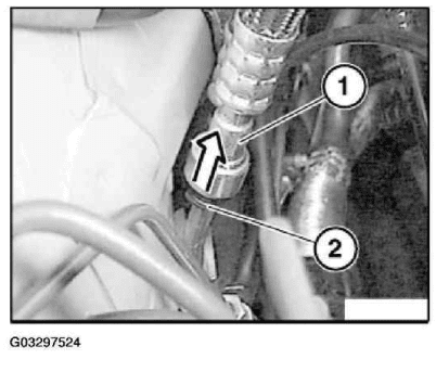
Fig. 21: Pressing Unlocking Ring Upwards And Detaching Fuel Hose
Courtesy of BMW OF NORTH AMERICA, INC.
M43, M44:
Cars with screw-mounted fuel feed line (2):
Follow installation instructions (1) and (2).
Installation instruction 1:
Always replace fuel hose (1) and hose clamps once they have been removed.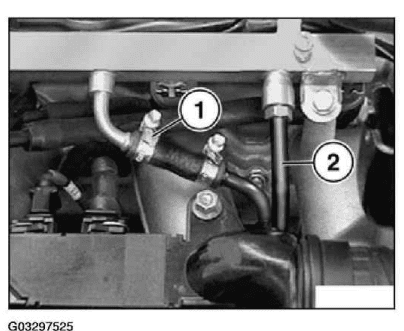
Fig. 22: Locating Screw-Mounted Fuel Feed Line (M43, 44)
Courtesy of BMW OF NORTH AMERICA, INC.
M43, M44:
Installation instruction 2:
Always replace O-ring. Coat O-ring with anti-friction agent.
Clean sealing faces of fuel feed line.
If necessary, replace fuel feed line.
For Tightening Torque, refer to 13 53 4A in FUEL SUPPLY SYSTEM – TIGHTENING TORQUES .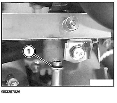
Fig. 23: Locating O-Ring (M43, 44)
Courtesy of BMW OF NORTH AMERICA, INC.
Seal off fuel hoses:
Fuel hoses with hose clamps:
Seal hoses with special tool 13 3 010.
Installation:
Fuel hoses and hose clamps must be replaced each time they are removed!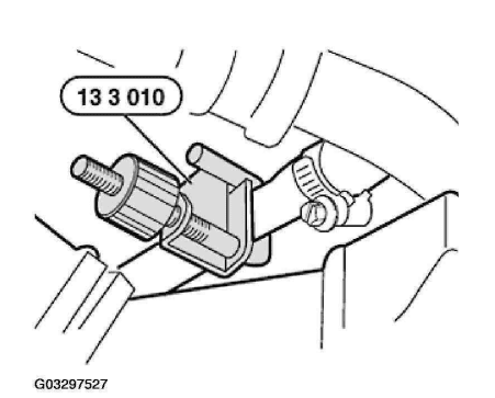
Fig. 24: Sealing Hoses With Special Tool
Courtesy of BMW OF NORTH AMERICA, INC.
Fuel hoses with quick-release couplings:
Seal fuel hoses (1) with special tool 13 5 281.
Seal fuel lines (2) with special tool 13 5 282.
Installation:
Check O-ring in fuel hose and sealing surfaces on fuel lines for damage; replace components if necessary.
Coat O-ring for assembly with anti-friction agent.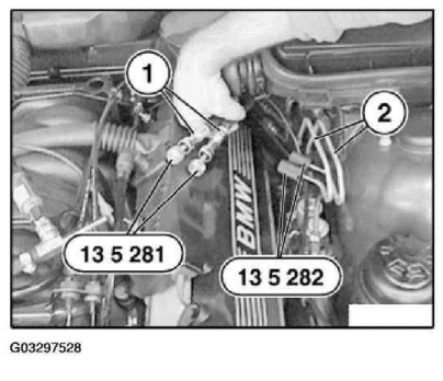
Fig. 25: Sealing Hoses And Fuel Lines With Special Tool
Courtesy of BMW OF NORTH AMERICA, INC.
THROTTLE AND OPERATION
13 54 030 REMOVING AND INSTALLING/SEALING THROTTLE ASSEMBLY (M54)
Necessary preliminary tasks:
z Switch off ignition
z Disconnect battery negative lead from battery and lay to one side
Follow 12 00… INSTRUCTIONS FOR DISCONNECTING AND CONNECTING BATTERY .
z If fitted (E85): remove sound generator . See 13 74 001 Removing And Installing/Replacing Sound
Generator (M54)
z Remove air intake hose . See 13 54 250 Replacing Intake Hose (Between Air-Mass Flow Sensor And
2005 BMW Z4
2003-05 BMW Z4 ENGINE PERFORMANCE Fuel System – Repair Procedures – Z4/E85
Connecting Piece) (M54) or 13 54 251 Replacing Intake Hose (Between Connecting Piece And
Throttle Assembly) (M54) .
Release screws (1) of cable duct mounting.
Place cable channel to one side.
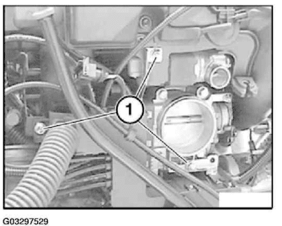
Fig. 26: Releasing Cable Duct Mounting Screws
Courtesy of BMW OF NORTH AMERICA, INC.
Unlock plug (1) and detach from throttle assembly (3).
Release screws (2) and remove throttle assembly (3).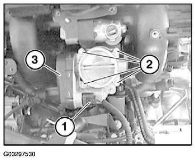
Fig. 27: Removing Throttle Assembly
Installation:
Replace sealing ring (1) on throttle assembly (2).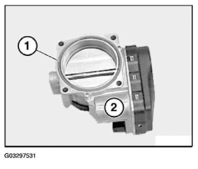
Fig. 28: Replacing Throttle Assembly Sealing Ring
Courtesy of BMW OF NORTH AMERICA, INC.
13 54 250 REPLACING INTAKE HOSE (BETWEEN AIR-MASS FLOW SENSOR AND
CONNECTING PIECE) (M54)
Necessary preliminary tasks:
z Switch off ignition.
z Remove top section of air cleaner housing. . See 13 72 001 Replacing Air Cleaner Element (M54) .
z Remove air-mass flow sensor. . See 13 62 560 Removing And Installing/Replacing Airmass Flow
Sensor (M54) .
Loosen hose clamp.
Remove intake hose (1).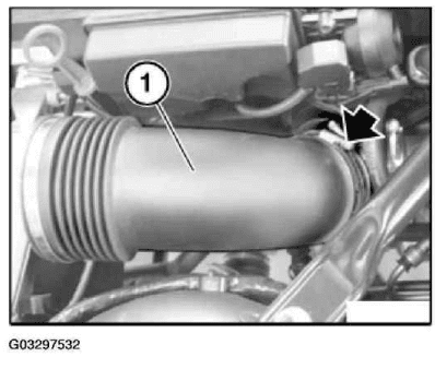
Fig. 29: Removing Intake Hose
Courtesy of BMW OF NORTH AMERICA, INC.
13 54 251 REPLACING INTAKE HOSE (BETWEEN CONNECTING PIECE AND THROTTLE
ASSEMBLY) (M54)
Necessary preliminary tasks:
z Switch off ignition.
z Disconnect intake hose.
Release hose clamps (1).
Remove vacuum hose.
Detach intake hose (2) from throttle assembly and idle speed control valve.
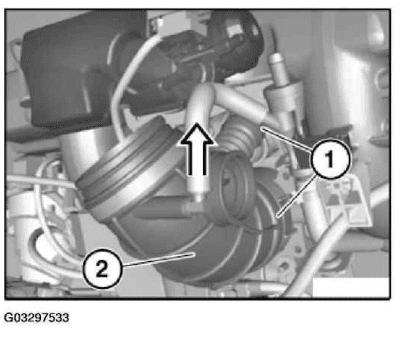
Fig. 30: Detaching Intake Hose From Throttle Assembly And Idle Speed Control Valve
Courtesy of BMW OF NORTH AMERICA, INC.
SENSOR FOR CONTROL UNIT BMW Z4
13 62 531 REPLACING COOLANT TEMPERATURE SENSOR (M52TU, M54)
Turn off ignition.
Installation location:
Coolant temperature sensor (1) is fitted below intake air manifold in cylinder head of cylinder 6.
Remove intake air manifold.
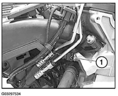
Fig. 31: Locating Coolant Temperature Sensor
Courtesy of BMW OF NORTH AMERICA, INC.
Disconnect plug connection (1).
Unscrew temperature sensor.
Installation:
Tightening torque, see 13 62 2AZ in FUEL SUPPLY SYSTEM – TIGHTENING TORQUES .
Check coolant level, top up coolant if necessary.
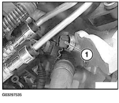
Fig. 32: Disconnecting Plug Connection
Courtesy of BMW OF NORTH AMERICA, INC.
Check stored fault messages.
Rectify faults.
Then clear fault memory.
13 62 560 REMOVING AND INSTALLING/REPLACING AIRMASS FLOW SENSOR (M54)
Necessary preliminary tasks:
z Read out fault memory of DME control unit.
z Switch off ignition.
NOTE: Read out fault memory of DME control unit.
2005 BMW Z4
2003-05 ENGINE PERFORMANCE Fuel System – Repair Procedures – Z4/E85z Remove upper intake filter housing section.
Unlock plug (1) and remove.
Loosen hose clamp.
Pull air-mass flow sensor (2) from air intake hose.
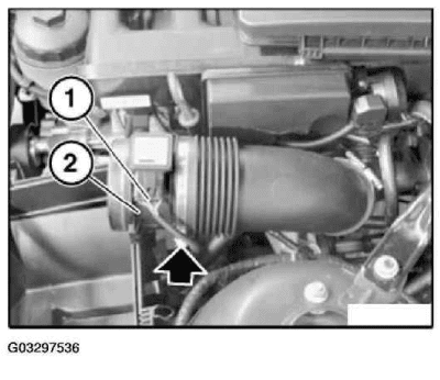
Fig. 33: Removing Air-Mass Flow Sensor From Air Intake Hose
Courtesy of BMW OF NORTH AMERICA, INC.
Installation:
Check sealing ring (1) between air-mass flow sensor and intake filter housing for damage, replace if necessary.
NOTE: Illustrations show E85.
2005 BMW Z4
2003-05 ENGINE PERFORMANCE Fuel System – Repair Procedures – Z4/E85Coat sealing ring (1) with suitable antiseize agent.
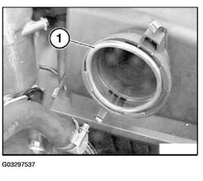
Fig. 34: Locating Sealing Ring
Courtesy of BMW OF NORTH AMERICA, INC.
Installation:
Arrow on air-mass flow sensor indicates direction of air flow.
Install air-mass flow sensor between intake filter housing and intake hose so that arrow points in direction of
intake hose.
NOTE: Illustrations show E85.
NOTE: Illustrations show E85.
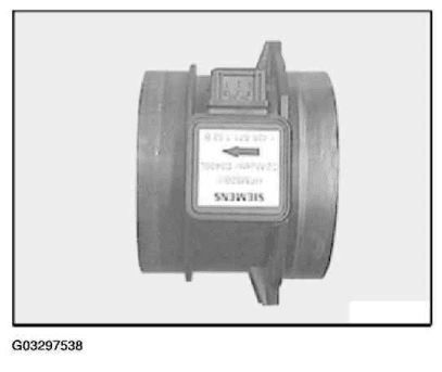
Fig. 35: Identifying Air-Mass Flow Sensor Air Flow Direction
Courtesy of BMW OF NORTH AMERICA, INC.
Unfasten hose clip (1).
Unlock plug (2) and remove.
Pull hot-film air-mass flow sensor (3) off air intake hose.
Installation:
Observe throughflow direction (4).
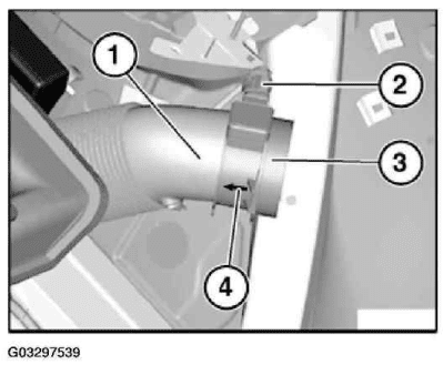
Fig. 36: Removing Air-Mass Flow Sensor From Air Intake Hose
Courtesy of BMW OF NORTH AMERICA, INC.
Check sealing ring (1) for damage and replace if necessary.
Secure sealing ring (1) in upper air filter housing section.
Attach sealing ring (2) to air-mass flow sensor.
Installation:
Coat all sealing rings with suitable antiseize agent.
IMPORTANT: Risk of damage to measuring electronics.
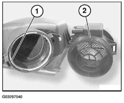
Fig. 37: Checking Sealing Ring
Courtesy of BMW OF NORTH AMERICA, INC.
Installation:
Check stored fault messages.
Now clear the fault memory.
START VALVES
13 64 541 REPLACING ALL FUEL INJECTORS
Necessary preliminary tasks:
z Switch off ignition
z Remove Complete Injection Pipe .
2005 BMW Z4
2003-05 ENGINE PERFORMANCE Fuel System – Repair Procedures – Z4/E85
Detach retainer (1).
Detach fuel injector from injection pipe.
Installation:
Check sealing rings, replace if necessary.
Insert fuel injector fully into injection pipe then pull out until groove is flush with edge of injection pipe.
Push on retainer.
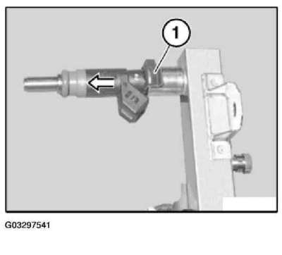
Fig. 38: Detaching Retainer
Courtesy of BMW OF NORTH AMERICA, INC.
Installation:
Coat sealing rings of fuel injectors with anti-seize agent to facilitate fitting of injection pipe.
2005 BMW Z4
2003-05 ENGINE PERFORMANCE Fuel System – Repair Procedures – Z4/E85
INTAKE SILENCER
13 71 000 REMOVING AND INSTALLING INTAKE FILTER HOUSING (M54)
Necessary preliminary tasks:
z Switch off ignition.
z Remove top section of intake filter.
Unfasten screws.
Remove intake filter housing (1).
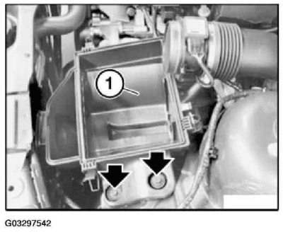
Fig. 39: Removing Intake Filter Housing
Courtesy of BMW OF NORTH AMERICA, INC.
Installation:
2005 BMW Z4
2003-05 ENGINE PERFORMANCE Fuel System – Repair Procedures – Z4/E85
Install guide rail (1) on intake filter housing on rubber mount (2).
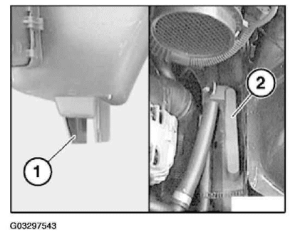
Fig. 40: Installing Guide Rail On Intake Filter Housing On Rubber Mount
Courtesy of BMW OF NORTH AMERICA, INC.
13 74 001 REMOVING AND INSTALLING/REPLACING SOUND GENERATOR (M54)
Loosen hose clamp.
Open quick-release coupling (1) on rear side.
Withdraw sound generator (2) from intake pipe and sound pipe (3) and remove.
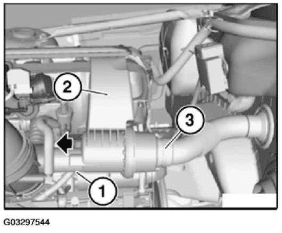
Fig. 41: Removing Sound Generator From Intake Pipe And Sound Pipe
Courtesy of BMW OF NORTH AMERICA, INC.
AIR CLEANER
13 72 001 REPLACING AIR CLEANER ELEMENT (M54)
E85 only:
Open clips (1).
Open retainers (2) on air-mass flow sensor.
Lift top section (3) of intake filter housing.
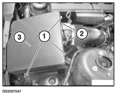
Fig. 42: Removing Intake Filter Housing Top Section (E85)
Courtesy of BMW OF NORTH AMERICA, INC.
BMW Z4 E53, E46 and E85:
Remove air cleaner element.
Installation:
Clean top and bottom sections of intake filter housing from inside.
Install new air cleaner element.
Check seal between air-mass flow sensor and air cleaner top section for damage, replace if necessary.
Coat seal with antiseize agent to facilitate joining of air cleaner and throttle body.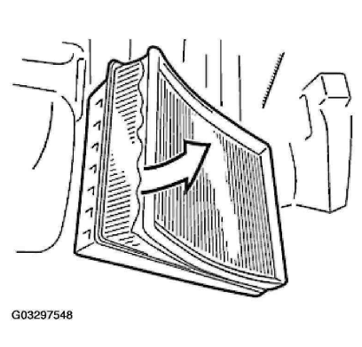
Fig. 43: Removing Air Cleaner Element
CARBON CANISTER VENTILATION
13 90 500 REPLACING TANK VENT VALVE (M54)
Necessary preliminary tasks:
z Check stored fault messages
z Switch off ignition
Installation location:
Tank vent valve is fitted at front on intake air manifold.
Unlock and detach plug connection (1).
Unlock and detach vent hose (2).
Remove hose (3).
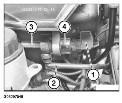
Fig. 44: Detaching Vent Hose
Rectify faults.
Now clear the fault memory.
NOTE: Read out fault memory of DME control unit.