VW GOLF TIMING CHAIN 2015 – 2017
Engine Mechanical, VW GOLF TIMING CHAIN
Engine ID : CNT A – CNS A – CXB B – CNS B – CXC A – CXC B
1 – Bolt
❑ 4 Nm + 90°
❑ Replace after removing
2 – Chain Tensioner
❑ Is under tension
❑ Secure using Tensioner
Locking Tool – T40267-
before removing
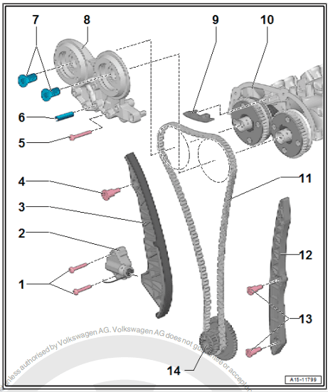
3 – Timing Chain Tensioning
Rail
4 – Guide Pins
❑ 20 Nm
5 – Bolt
❑ Replace after removing
❑ Tightening specification
and sequence for bear‐
ing bracket with steel
bolts.
❑ Tightening specification
and sequence for bear‐
ing bracket with alumi‐
num bolts.
6 – Mounting Sleeve
❑ Depending on the ver‐
sion, not present on every bearing bracket
❑ Pulled into the cylinder head with the bolt
7 – Pilot Valves
❑ 35 Nm
❑ Left thread
❑ Removing using Assembly Tool – T10352/2-
8 – Bearing Bracket
❑ Depending on the version with adapter sleeve. Refer to the Parts Catalog for the allocation.
❑ Tightening specification and sequence for bearing bracket with steel bolts. Refer to
❑ Tightening specification and sequence for bearing bracket with aluminum bolts. Refer to
9 – Camshaft Timing Chain Guide Rail
10 – Camshaft Housing
11 – Camshaft Timing Chain
❑ Before removing, mark the direction of rotation with paint
12 – Camshaft Timing Chain Guide Rail
13 – Guide Pins
❑ 20 Nm
14 – Three Stage Chain Sprocket
❑ Crankshaft
❑ Installed position. Refer to ⇒ Fig. ““Three Stage Chain Sprocket – Installed Position”“ , page 116
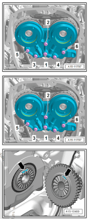
Tightening Specification and Sequence for Bearing Bracket with
Steel Bolts
– Tighten the bolts in steps in the sequence shown:
Step Bolts Tightening Specifications
1. -1- 3 Nm
2. -1 to 6- 9 Nm
Tightening Specification and Sequence for Bearing Bracket with
Aluminum Bolts
– Tighten the bolts in steps in the sequence -1 to 6-:
Step Bolts Tightening Specification/Additional
Turn
1. -1- through -6- 4 Nm
2. -1- through -6- 180° additional turn
Three Stage Chain Sprocket – Installed Position
• Both surfaces must -arrows- must line up across from each
other.
VW GOLF TIMING CHAIN
3.2 Overview – Balance Shaft Drive Chain
Note
♦ After performing work on the chain drive the adaptation value
in the engine control module must be adapted. To do this turn
on the ignition and select the following menu items on the Ve‐
hicle Diagnostic Tester :
♦ 01 – Engine electronics
♦ Guided functions
♦ 01 – Adaptation after repair work on the chain
drive
VW GOLF TIMING CHAIN

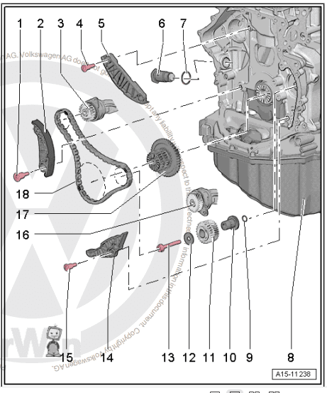
1 – Guide Pin
❑ 20 Nm
2 – Tensioning Rail
❑ For the timing chain
3 – Balance Shaft
❑ Exhaust side
❑ Must be replaced after
removing
❑ Lubricate the bearing
with engine oil
❑ Replacing. Refer to
4 – Guide Pin
❑ 20 Nm
5 – Guide Rail
❑ For the timing chain
6 – Chain Tensioner
❑ 85 Nm
❑ Install with locking fluid.
Refer to the Parts Cata‐
log.

7 – Seal
8 – Cylinder Block
9 – O-Ring
❑ Coat with engine oil
10 – Mounting Pin
❑ Lubricate with engine oil
❑ Installed position.
11 – Intermediate Sprocket
❑ The intermediate sprocket must be replaced if the bolt -item 13- ⇒ Item 13 (page 117) is loosened.
12 – Thrust Washer
13 – Bolt
❑ Replace after removing
❑ The intermediate sprocket -item 11- must be replaced if the bolt is loosened.
❑ Tightening sequence. Refer to
14 – Guide Rail
❑ For balance shaft timing chain
15 – Guide Pin
❑ 20 Nm
16 – Balance Shaft

❑ Intake side
❑ Must be replaced after removing
❑ Lubricate the bearing with engine oil
❑ Replacing.
17 – Three Stage Chain Sprocket
❑ Installed position.
18 – Balance Shaft Drive Chain
❑ Removing and installing. Refer to
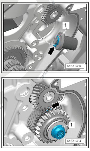
Mounting Pins – Installation Position
• Replace and lubricate the O-Ring -1-
• The alignment pin -arrow- for the bearing pins must engage in
the hole in the cylinder block.
• Lubricate the bearing pins
Intermediate Sprocket Tightening Sequence
Note
♦ Always replace the intermediate sprocket. Otherwise the
backlash will not adjust itself and it could result in engine dam‐
age.
♦ The new intermediate sprocket has an anti-friction coating that
wears off after a short period of use, which automatically ad‐
justs the backlash.

Step Bolts Tightening Specification/Addi‐
tional Turn
1. -1- 10 Nm
2. -1- The intermediate sprocket
must not have any play. Loos‐
en and tighten it again if nec‐
essary.
3. -1- 25 Nm
4. -1- Turn an additional 90°
3.3 Camshaft Timing Chain, Removing and
Installing
Special tools and workshop equipment required
♦ Assembly Tool – T10352/2-
♦ Counterhold – Vibration Damper – T10355-
♦ Locking Pin (3 pc.) – T40011-
♦ Chain Tensioner Lever – T40243-
♦ Tensioner Locking Tool – T40267-
♦ Camshaft Locks – T40271-
♦ Adapter – T40266-
♦ Assembly Tool – T10531-
♦ Individual components of the Assembly Tool – T10531- :
♦ Mount – T10531/1-
♦ Tensioning Pins – T10531/2-
♦ Turning Over Tool – T10531/3-
♦ Collar Nut – T10531/4-
Caution

This procedure contains mandatory replaceable parts. Refer
to component overview prior to starting procedure.
Mandatory Replacement Parts
♦ Bolts – Bearing Bracket
♦ Bolt – Intermediate Sprocket
Removing
– Remove the noise insulation.
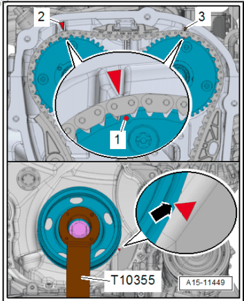
– Turn the vibration damper with the Counterhold – Vibration
Damper – T10355- to the “Top Dead Center (TDC) point”.
• The markings -1- on the camshaft chain sprockets must be
opposite the markings -2 and 3-.
• The notch on the vibration damper and the marking on the
lower cover for timing chain -arrow- must be opposite one an‐
other.
Note
The pilot valve has left-hand threads.

– Remove the left and right pilot valves using the Assembly Tool
– T10352/2- in the direction of the -arrow-.
– Remove the bolts -arrows- and remove the bearing bracket.
– Remove the bolts -arrows-.
– Install the Chain Tensioner Lever – T40243- in direction of
-arrows-.
– Press the chain tensioner locking ring -1- together and hold it.
– Slowly press and hold the Chain Tensioner Lever – T40243-
in the direction of -arrow-.
– Secure the chain tensioner with the Tensioner Locking Tool –
T40267- .
– Remove the Chain Tensioner Lever – T40243- .
– Bolt the Camshaft Lock – Component 2 – T40271/2- to the cyl‐
inder head and slide into the splines on the chain sprocket in
the direction of the -arrow 2-. Rotate the intake camshaft with
the Adapter – T40266- -1- if necessary.
– Install the Camshaft Lock – Component 1 – T40271/1- on the
cylinder head.

For the following steps a second technician is necessity.
– Hold the exhaust camshaft with the Adapter – T40266- in the
direction of the -arrow A-. Remove the bolt -1- and guide the
tensioning rail -2- downward. Turn the camshaft clockwise in
direction of -arrow A- until the Camshaft Lock – Component 1
– T40271/1- can be pushed in the chain sprocket splines -C-.
– Remove the guide rail -1- by unlocking the latch -arrow- with
a screwdriver and pushing the guide rail forward.
– Remove the bolts -arrows- and remove the chain tensioner
-1-.
– Press the oil pump chain tensioner bracket in direction of
-arrow- and lock with Locking Pin (3 pc.) – T40011- .
– Remove the bolt -1- and remove the chain tensioner.
– Remove the bolts -1- and remove the glide rail -2-.
– Remove the camshaft timing chain from the camshaft sprocket
and hang it on the camshaft pins -arrows-.
– Remove the chain tensioner -1- for the balance shaft timing
chain.
– Remove the bolts -1-. Remove the tensioning rail -2- and the
glide rails -3 and 4-.

– Loosen the adjusting bolt -A- and remove the tensioning pin
-B-.
– Remove the oil pump drive timing chain to remove the three
stage chain sprocket.
– Remove the camshaft timing chain and drive chain for the bal‐
ance shaft.
Installing
– Check that the crankshaft is at Top Dead Center (TDC). The
flat area on the crankshaft -arrow- must be horizontal.
– Draw the markings on the cylinder block -1-, as shown, with a
waterproof marker.
3. Chain Drive
– Draw a marking -2- on the three stage chain sprocket tooth
-1- with a waterproof marker.
– Turn the intermediate sprocket and balance shaft to the mark‐
ings -arrow-, do not loosen the bolt -1-.
VW GOLF TIMING CHAIN

Note
♦ The painted links of the chain must be positioned on the mark‐
ings on the chain sprockets.
♦ Do not pay attention to the position of any additional painted
chain links that may also be present.
– Lay the balance shaft drive chain, and position the painted
links -arrows- with the markings on the chain sprockets.
– Install the guide track -1- and tighten bolts -arrows-.
– Engage the camshaft timing chain with the painted links
-arrows- on the camshaft pins.
– Lay the oil pump drive timing chain onto the three stage chain
sprocket.
– Tilt the three stage chain sprocket in the direction of the
-arrow- toward the engine and secure it to the crankshaft. The
marking -arrows- must be positioned opposite each other.
1. Install the Tensioning Pins – T10531/2- in the crankshaft and
tighten hand-tight.
2. Install the Turning Over Tool – T10531/3- . Tighten the
Knurled Nut – T10531/4- hand tight. Using a 32 mm open
end wrench move the Turning Over Tool – T10531/3- back
and forth slightly while doing this tighten the Knurled Nut –
T10531/4- until the chain sprocket is seated securely on the
crankshaft splines. Now tighten the adjusting bolt -A-.

– Position the painted chain link in the balance shaft drive chain
-arrow- at the marking on the three stage chain sprocket. In‐
stall the tensioning rail -1- and the glide rail -2-. Tighten bolts
-3-.
– Install the chain tensioner -1-.
– Check the adjustment again. The painted chain links
-arrows- must line up with the markings on the chain sprock‐
ets.
– Place the camshaft timing chain on the intake camshaft, ex‐
haust camshaft and the crankshaft. Position the painted chain
links -arrows- on the markings on the chain sprockets.
– Install the guide rail -2- and tighten the bolts -1-.
– Install the upper glide rail -1-.
For the following steps a second technician is necessity.
– Turn the exhaust camshaft with the Adapter – T40266- slightly
in the direction of -arrow A- and push the Camshaft Lock –
Component 1 – T40271/1- from the camshaft splines in the
direction of -arrow B-. Release the camshaft in the direction in
the direction of -arrow C-, until the timing chain touches the
glide rail -1-. Hold the camshaft in this position, install the ten‐
sioning rail -2- and tighten the bolts -3-.
– Install the chain tensioner -1- and tighten the bolts -arrows-.
– Install the chain tensioner -2-. The wire clip -arrow- must come
in to contact with the oil pan upper section opening. Tighten
the bolt -1- and remove the Locking Pin (3 pc.) – T40011- .
– Turn the intake camshaft in the direction of the arrow -1- using
the Adapter – T40266- until the Camshaft Lock – T40271/2-
-2- can be pushed out of the chain sprocket splines. Release
the camshaft.
– Remove the Camshaft Lock – Component 1 – T40271/1- and
Camshaft Lock – Component 2 – T40271/2- .
– Check the adjustment. The painted chain links -arrows- must
line up with the markings on the chain sprockets.
– Install the bolts -arrows- and tighten them. Tightening specification.
– Lubricate the holes -arrows- with engine oil.
Note
Adapter sleeve -1- is not present on every bearing bracket.
– Attach the bearing mount. Do not tilt it when doing this. Handtighten the bolts -arrows-.
– Remove the Tensioner Locking Tool – T40267- .
– Tighten the bearing bracket bolts -item 5-
– Install the pilot valves
– Let the engine turn a second time in the direction of engine rotation.
Note
Due to the ratio, the painted chain links no longer match up after the engine has been turned.
– Remove the turning over tool and install the lower timing chain
cover. Refer to ⇒ page 109 .
Note
Tighten the bolts -1 and 4- with an additional turn after installing
the vibration damper. The bolts must be removed again to install
the vibration damper.
– Install the vibration damper.
– Install the upper timing chain cover.
– Install the ribbed belt tensioning damper.
– Install the ribbed belt.
The rest of the installation is performed in reverse order of removal, noting the following:
– After performing work on the chain drive the adaptation value
in the Engine Control Module (ECM) must be adapted. To do
this turn on the ignition and select the following menu items on
the Vehicle Diagnostic Tester :
♦ 01 – Engine Electronics
♦ Guided Functions
♦ 01 – Adaptation After Repair Work On the Chain Drive
HOME

